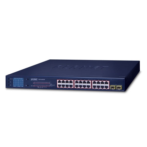
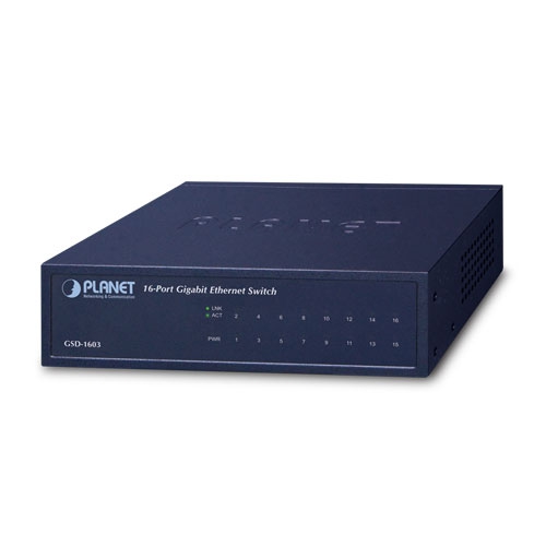
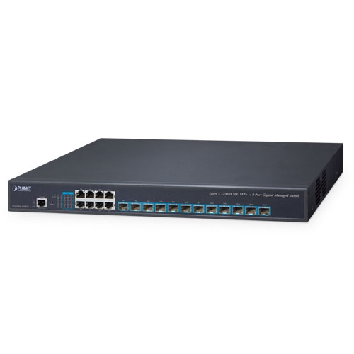
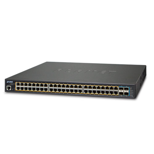
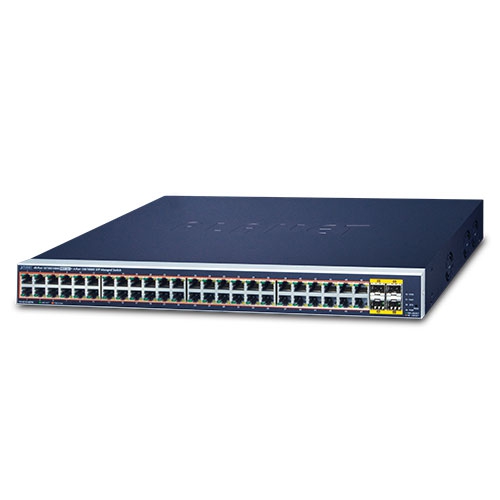
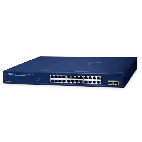
Industry-leading Integration of PoE Technology and Renewable Power System
PLANET’s newly-launched Renewable Energy Industrial 802.3at PoE Managed Ethernet Switch, BSP-360, is designed for deploying a surveillance or wireless network and remotely monitoring and managing the IP-based devices. Based on its green technology, the BSP-360 can be charged by the inexhaustible and natural source of energy, such as solar, wind and hydroelectric power to conserve energy so as to economically power these remote IP cameras and wireless APs, especially used for such expansive applications as dams, forests, deserts, national parks, nature/animal protection areas and highways.
PLANET NMS-360 Network Management Controller can centrally manage up to 512 BSP-360 units and 2,048 PLANET IP cameras via MQTT and ONVIF Protocols. (Please regularly check PLANET website for the latest compatibility list of managed devices.)
MPPT (Maximum Power Point Tracking) Charge Controller
An MPPT (Maximum Power Point Tracker) is an electronic DC to DC converter that optimizes the match between the PV solar panels and the battery bank or utility grid. They convert a higher voltage DC output from solar panels (and a few wind generators) to the lower voltage needed to charge the battery effectively.
Zero-Carbon and Stable Power Supply
The nickel-cadmium or lead-acid battery gets recharged by way of the BSP-360 where solar power is sourced. Thus, the BSP-360 will keep powering PD devices without the need of any cabling. Its zero-carbon feature is made possible as the energy the unit gets is renewable. Most importantly, the operation of outdoor wireless IP-based surveillance can be continued into the night as the battery is charged during the day.
Smart Battery Management
The BSP-360 features the following special power management functions:
Current Battery Usage Status
The administrator can remotely access the BSP-360 to know the power status of the battery and renewable energy, and the estimated time of power consumption.
Low Voltage Cut-Off Protection
If the remaining energy is too low to power the network, the system will automatically power off the device to make sure the system works normally, and an alert is then sent to the administrator at the same time.
Smart PoE PD Management including PLANET ONVIF IP carmera
As it is the managed PoE switch for surveillance, wireless and VoIP networks, the BSP-360 features the following special PoE management functions:
ONVIF management functions:
Intelligent Powered Device Alive Check
The BSP-360 can be configured to monitor connected PD (Powered Device) status in real time via ping action. Once the PD stops working and responding, the BSP-360 will resume the PoE port power and bring the PD back to work. It will greatly enhance the network reliability through the PoE port resetting the PD’s power source and reducing administrator management burden.
Scheduled Power Recycling
The BSP-360 allows each of the connected PoE IP cameras or PoE wireless access points to reboot at a specific time each week. Therefore, it will reduce the chance of IP camera or AP crash resulting from buffer overflow.
PoE Schedule for Energy Saving
Under the trend of energy saving worldwide and contributing to environmental protection, the BSP-360 can effectively control the power supply besides its capability of giving high watts power. The “PoE schedule” function helps you to enable or disable PoE power feeding for each PoE port during specified time intervals and it is a powerful function to help SMBs or enterprises save power and budget. It also increases security by powering off PDs that should not be in use during non-business hours.
PoE Usage Monitoring and Intelligent LED Indicator for Real-time PoE Usage
Via the power usage chart in the web management interface, the BSP-360 enables the administrator to monitor the status of the power usage of the connected PDs in real time. Thus, it greatly enhances the management efficiency of the facilities. Moreover, the BSP-360 helps users to monitor the current status of PoE power usage easily and efficiently via its advanced LED indication. Called “PoE Power Usage”, the front panel of the BSP-360 has three LED indicators of different power usages.
User-friendly and Secure Management
For efficient management, the BSP-360 is equipped with web and SNMP management interfaces. With the built-in web-based management interface, the BSP-360 offers an easy-to-use, platform-independent management and configuration facility. By supporting the standard SNMP, the switch can be managed via any standard management software.
Solar PoE Power Supply for Long Distance Wireless Surveillance Solution
The BSP-360 PoE Managed Switch can be deployed anywhere in the city where there is no direct AC electricity. With PoE over the Cat5 cable, wireless AP and SFP media converter, you can check the current energy consumption and battery status in your office within the configuration interface of the BSP-360.
SOHO/Home-Use Gigabit Ethernet PoE Network Deployment
With its expanded home-use feature, the BSP-360 Renewable Energy PoE Switch helps SOHO/home users to create an integrated network where power is so easily utilized for transmission of data and video. It integrates IEEE 802.3at PoE technology and renewable power system. The wireless AP and PoE IP camera devices work perfectly with the BSP-360, which injects power through the Ethernet cables, thus helping SOHO/home users to build a cost-effective and reliable PoE network environment easily.
Economical Central Energy Management Solution for SMBs
PLANET NMS-360 Renewable Energy Management Controller allows users to remotely monitor the statuses of the BSP-360-powered devices in real time, including green power status, average power usage, instant PoE usage, and so on. Through the remote web management, the administrator at the headquarters is able to monitor and control those remote powered devices powered by the BSP-360.
The BSP-360’s built-in four 802.3at/802.3af PoE ports allow the administrator to flexibly install PoE wireless APs in remote areas, without worrying about locating extra electric outlets. When functioning with a pair of the wireless transmission units, the BSP-360 Renewable Energy PoE Switch/Router can be efficiently managed from a remote control center.
**To get the best performance, match it with PLANET devices for outdoor wireless bridge applications.
Extension of Network Deployment with Fiber Media Converter
With the 24VDC out interface, the BSP-360 enables you to supply power to other devices, such as PLANET IGT-905A fiber media converter where high-speed and stable data transmission can be made to a remote core network. It can extend the distance to a maximum of 120 kilometers between the BSP-360 and control center via fiber-optic link.
Physical Port
Power over Ethernet
Battery Management
Industrial Case and Installation
Switching
Router
Security
Management
Hardware Specifications | |
---|---|
Copper Ports | LAN: 5 10/100/1000Mbps auto MDI/MDI-X RJ45 port (Port 1 to Port 5, bridge mode) WAN: 1 10/100/1000Mbps auto MDI/MDI-X RJ45 port (Port 5, gateway mode) |
PoE Injector Port | 4 ports with 802.3af/802.3at PoE injector function (Port 1 to Port 4) |
USB | 1 USB Type A female for setting backup |
Power Output | 4 PoE out 51VDC; max. 30 watts per PoE port 2 DC out 24@ 1A maximum (four-pin terminal block) * The voltage of DC out is based on the battery. |
Switch Architecture | Store-and-Forward |
Switch Fabric | 10Gbps/non-blocking |
Switch Throughput@64 bytes | 5.95Mpps@64 bytes |
MAC Address Table | 8K entries |
Shared Data Buffer | 512Kbit |
Flow Control | IEEE 802.3x pause frame for full duplex Back pressure for half duplex |
Reset Button | < 5 sec: System reboot > 5 sec: Factory default |
LED Indicators | 3 LEDs for System and Power: Green: Power Red: Fault Green: System 4 LEDs for PoE Copper Ports (Port 1~Port 4): Green: LNK/ACT Orange: PoE-in-use 1 LED for 10/100/1000T Copper Port (Port 5): Green: LNK/ACT 3 LEDs for PoE Power Usage (W) Orange: 50, 100 and 120W |
Connector | Removable 6-pin terminal block Pin 1/2 for PV panel; Pin 3/4 for alarm; Pin 5/6 for battery |
Alarm | 1 digital output (DO): Level 0: -24V~2.1V (±0.1V) Level 1: 2.1V~24V (±0.1V) Open collector to 24V DC, 100mA max. |
Power Requirements | PV in: 24~45V DC Battery in/out: 24V DC |
Power Consumption/ Dissipation | 5.04 watts, 17.1BTU (Standby without PoE function) 6.96 watts, 23.7 BTU (Full loading without PoE function) 135.36 watts, 461.5 BTU (Full loading with PoE function) |
Dimensions (W x D x H) | 89 x 107 x 152 mm |
Weight | 1026g |
ESD Protection | 6KV DC |
Enclosure | IP30 aluminum case |
Installation | DIN-rail kit and wall-mount ear |
Power over Ethernet | |
PoE Standard | IEEE 802.3af/802.3at Power over Ethernet PSE |
PoE Power Supply Type | End-span |
PoE Power Output | Per port 51V DC, 275mA. Max. 15.4 watts (IEEE 802.3af) Per port 51V DC, 535mA. Max. 30 watts (IEEE 802.3at) |
Power Pin Assignment | 1/2 (+), 3/6 (-) |
PoE Power Budget | 120 watts (PoE consumption + DC out and depending on power input) |
Max. Number of Class 2 PDs | 4 |
Max. Number of Class 3 PDs | 4 |
Max. Number of Class 4 PDs | 4 |
Electrical Characteristics | |
System Voltage Rating | 24V DC |
Maximum Input Current | 6A (System with Over Current Protection) |
Max. Solar Array VOC | 60V DC |
Max. Operating Voltage | 45V DC |
Total Current Consumption | While operating -32mA At idle -11mA |
High Temperature Shutdown | 100 degrees C (disconnect solar and loading) 80 degrees C (reconnect solar and loading) |
Battery Charging Characteristics | |
Charge Algorithm | The design presently uses ‘perturb and observe’ algorithm for MPP tracking. |
Maximum Output Current | 6A |
Lead Acid Battery (Default Setting) | ± 60 mV/degrees Celsius for lead acid type batteries; charge cut-off @ 55 degrees C (Temperature compensation baseline@ 25 degrees C) |
Float Charge Voltage | DC 27.2V (26.0~30.0V) |
Absorption Charge Voltage | DC 29.2V (28.0~32.0V) |
LVD (Low Voltage Disconnection) | DC 22.2V (21.0~25.0V) |
LVR (Low Voltage Reconnection) | DC 22.4V (23.0~27.0V) |
Router Features | |
Internet Connection Type | Shares data and Internet access with users, supporting the following internet accesses:
|
Firewall | NAT firewall with SPI (Stateful Packet Inspection) Built-in NAT server supporting Port Forwarding, and DMZ Built-in firewall with IP address/MAC address/Port/ URL filtering Supports ICMP-FLOOD, UDP-FLOOD, TCP-SYN-FLOOD filter, DoS protection |
Routing Protocol | Static/Dynamic (RIP1 and 2) routing |
VPN Pass-through | PPTP, L2TP, IPSec, IPv6 |
LAN | Built-in DHCP server supporting static IP address distribution Supports UPnP, Dynamic DNS Supports IGMP Proxy Supports 802.1d STP (Spanning Tree) IP/MAC-based bandwidth control |
Management | |
Management Interface | Setting up of system/management functions Web firmware upgrade SNMP trap for alarm notification of events |
PoE Management | Power limit by consumption and allocation PoE admin mode Per port power schedule Per port power enable/disable Power feeding priority Current per port usage and status Total power consumption PD alive check Scheduled power recycling |
Battery Management | Current battery usage status Low voltage cut-off protection |
PLANET ONVIF IP Camera Management | Supports PLANET ONVIF IP camera discovery A maximum of four PLANET ONVIF IP cameras can be powered by one BSP-360 switch Supports IP camera snapshot function in the LAN |
Standards Conformance | |
Regulatory Compliance | FCC Part 15 Class A, CE |
Standards Compliance | IEEE 802.3 10BASE-T Ethernet IEEE 802.3u 100BASE-TX Fast Ethernet IEEE 802.3ab 1000BASE-T Gigabit Ethernet IEEE 802.3x Flow Control and Back Pressure IEEE 802.1D Spanning Tree Protocol IEEE 802.3af Power over Ethernet IEEE 802.3at Power over Ethernet Plus RFC 768: UDP RFC 791: IP RFC 2068 HTTP RFC 1157: SNMP v1 RFC 1902: SNMP v2c RFC 5424: Syslog |
Environment | |
Operating | Temperature: -10 ~ 60 degrees C Relative Humidity: 5 ~ 95% (non-condensing) |
Storage | Temperature: -10 ~ 70 degrees C Relative Humidity: 5 ~ 95% (non-condensing) |
Date | Version | Description | Download |
---|---|---|---|
2020-12-04 | 2.1 | BSP-360 |
![]() |
Date | Version | Description | Download |
---|---|---|---|
2020-10-30 | 2.253b201021 | Release for hardware version 2.0. 1. Supports NMS-360 (MQTT protocol) 2. Added ONVIF function 3. Added Geolocation |
![]() |
Date | Version | Description | Download |
---|---|---|---|
2020-10-30 | 2.1 | IGG modified for BSP-360(V2)support NMS-360
FW Version: v2.253b201021 |
![]() |
2019-08-26 | 2.0 | Initial Release For BSP-360(v2)_v2.0 |
![]() |
Ordering Information | |
---|---|
BSP-360 |
Industrial Renewable Power 5-Port Gigabit Managed Switch with 4-Port 802.3at PoE+ |